Description
In engineering, the field of application of gear trains is widespread, reaching from applications in large diesel engines to lifting system or connections in machine tools. In many fields, gears are leightweight constructed in order to enable a quick system response. Such gears underlie steady forces as well as high dynamic forces: the gear train in a diesel engine, which connects the aggregates such as pumps with each other, underlies highly alternating loads when it comes to gas forces. The gears get elastic deformed. Furthermore, dynamic effects such as gear hammering, that is when a tooth flank is lifted from its contact partner, hits the opposite flank of the next tooth and then bounces back and forth, may occur. Other effects are wave propagations through the gear or the changing number of teeth in contact. Such undesirable dynamic effects directly influence the durability of a gear system. Thereby, knowledge of technical values such as forces during impact are of special interest.
In industry, the modeling and simulation of gear trains is most often done using commercial multibody-system tools. When precise results are needed, the multibody-system approach (MBS) is not exact enough, because it does not allow elastic deformation and thus, effects such as the changing number of gears in contact during impact can not be simulated. An elastic formulation is needed. The method of finite elements (FEM) offers elastic treatment of the gears and precise results, but the systems are very large due to discretization purposes. This results in long computational times.
A good compromise between long computational times and result precision is offered by the method of elastic multibody-system (EMBS). The formulation allows small deformations as well as large rigid body motions. Both occur in highly loaded gears. The formulation is fast enough to calculate many impacts as well as whole rotations and produces good results, compared to FEM.

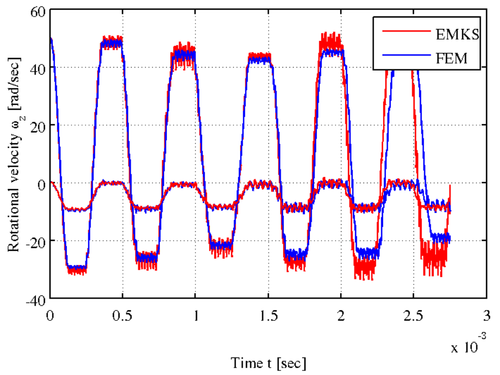
In figure 1, the FE-model of two gears is presented. Both teeth together have more than 300.000 nodes what leads to huge system matrices. At the same time, the EMBS-model is much smaller since it uses just some modes for the elastic description. Figure 2 compares the rotational velocity of both gears, once simulated using FEM and once using EMBS. The results of the two formulations are in good agreement whereas the computational time of the EMBS is much smaller.
Contact
